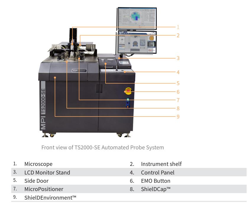
8寸全自动探针台
Taiwan MPIOverviewThe TS2000-SE from MPI...
咨询热线
18502873311Taiwan MPI
Overview
The TS2000-SE from MPI is the first ever 200 mm automated engineering probe system on the
market integrating innovative features specifically designed to reduce the cost of test. These
features are incorporated into the MPI ShielDEnvironmentTM for ultra-low noise, very accurate
and highly reliable DC/CV, RF and High Power measurements.

Microscope Movement
MPI TS2000-SE supports three microscope movements.
>5050ZUM-VM Linear XYZ Microscope Movement
>5050MLM-Manual XY Microscope Movement with 50 x 50 mm/140 mm Program Z
>A5050M-LM: 50 x 50 x 140 mm Linear Microscope movement controlled by SENTIO9.
SZ10, MZ12, EZ10, AMZ 12, AMZ12-LM, IMAG and IMAG -PRO microscopes are available for
the MPI TS2000-SE.
Operation of EZ10
1.Turn on the LED lighting and adjust to the maximum light intensity.
2. While watching the eyepieces the eyepieces of trinocular head and slide the interpu-
pillary by hands so that the right and left visual fields should be one. Interpupillary
distance has individual differences.
3. Read the interpupillary distance in scale at center. Adjust the diopter correction besi-
de the both eyepieces so that it becomes same values.
4. Determine the zoom ratio. Here, turn it to low magnification 0.85 x (high magnificati-
on 8.5x).
5. Set the aperture dial to 1 (5 for high magnification 8.5 x).
6. While watching the eyepieces, turn the focus knob (coarse adjustment of large dia-
meter, fine adjustment of small diameter) to focus on the DUT.
7. Turn again the aperture dial to match the contrast that is easy to see.
8. Repeat 6 to 7 again if changing the zoom ratio. For example, if you change the zoom
dial to high magnification 8.5 x, the aperture dial should be around 5 is recommen-ded.
9. Pull the optical path switching lever to the right. The optical path switches to the camera side, and you can see the image on the monitor. .
Operation Template
Place the calibration substrate on Aux-L chuck, load it from front door and follow the
steps below to start calibration.
1. For example, the wafer chuck was in load position. Press“Front Door”button, open
the front door and then place the calibration substrate on Aux-L chuck.
2. Close front door, press“Start" button, and then load the wafer chuck from front
door.
3. When the LED light of Front Door is switched off, press“Aux-L”button to switch to
Aux-L stage.
Press“Enable Z-Axis" button for three seconds, when the LED light of“Z-Axis" button
is on, press“FAST”in speed modes to switch to“FAST”mode.
5. Move Aux-L chuck height by pressing“Z-up”or“Z- down”button to catch the graphic
of calibration substrate.
6. When the outline of the calibration substrate can be seen, switch NORMAL, SLOW or
JOG mode to make fine height adjustment and clear graphic.
7. Use 2-pt alignment in SENTIO*.
To adjust, switch to FAST mode before setting up the first point and then move XY
stages by joystick. When moving to the point you wish to set up, switch to NORMAL
or SLOW mode to move to the exact point. Switch to JOG mode to execute fine
adjustment.
After setting up the first point, repeat the steps above, move to the second point you
wish to set up, press the second setting point and then SENTIOO will execute THETA
adjustment.
10. Repeat Step 8-9 till the theta of calibration substrate meets the standard and then
2-pt alignment is completed.